|
Acoustic Emission (AE) refers to the transient elastic waves resulting from local internal microdisplacements and stress redistribution within a material. AE events generate localized sources of high-frequency elastic waves that travel along the surface of a material.
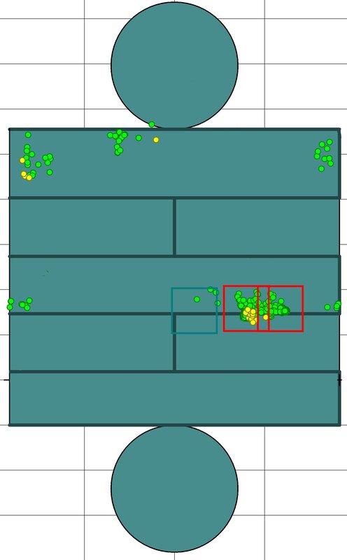
Why is AE Testing Important? Many catastrophic equipment failures in the industry have highlighted the need for periodic inspection of critical equipment and structures. Acoustic Emission (AE) testing is a nondestructive inspection technique that can be used either as a stand-alone inspection method or to complement other NDE techniques. AE testing takes advantage of high-frequency transient elastic waves emitted by active flaws in materials under stress. By using special sensors and data acquisition instruments, these emissions can be detected and utilized to accurately triangulate the location of each source. What is the AE Testing Process? Data analysis software designed explicitly for AE testing helps graphically identify active flaws and plot their locations in 2D and 3D diagrams. AE testing can evaluate the mechanical integrity of many types of pressure vessels, bridges, storage tanks, piping systems, and other mechanical structures. Typical frequency ranges of AE sensors vary between 20 kHz and 1 MHz, where sensor selection depends on the application and types of flaws to be detected. Long-term AE monitoring helps correlate environmental and process parameters to active damage and can be used to narrow follow-up inspection efforts and repair planning during equipment shutdown. Additionally, AE can help detect leak sources in structures that are otherwise difficult to inspect using conventional means. Data analysis procedures identify significant AE source location clusters through selective feature filtering, graphical analysis, and event cluster analysis. Data acquisition filtering records only those AE events that can be located within the source location array. Noises outside the structure being tested, such as pumps or other mechanical equipment, are not detected. Source location arrays can either be linear, between 2 adjacent sensors, or spatial in 2D or 3D representations with multiple sensors on a test object. Features of the test object, such as weld seams and nozzles, can be graphically represented within the data analysis software. |
Houston Engineering Solutions LLC
11757 Katy Freeway, Suite 1300, Houston, TX 77079, USA
Phone: +1 (832)838-4894
Web: www.HESengineers.com
Copyright © 2012 Houston Engineering Solutions, LLC All rights reserved
Phone: +1 (832)838-4894
Web: www.HESengineers.com
Copyright © 2012 Houston Engineering Solutions, LLC All rights reserved


